Getting your data to the Machines

Getting your data to the Machines

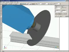
When we purchased our new machines, they came with the standard suite of Emmegi software: CamPlus, Job, Drill, and Shape.  The CamPlus software makes it easy to create your machinings.  The Job software is where you create the cutting information for each order you will send to the shop.  The Drill software is what converts the Job information into something the Machine can use.  Shape is for converting odd geometry into a machining.

The nice part of the Emmegi setup is that all the machines use the same software.  So if you start off with the planet, and then purchase the quadra, you can use the same software programs.  What they may not tell you is that the Job software has a text based interface.  It requires a USB driver that you plug into your computer and it allows you to import text data into Job.  When you go to purchase your machines, make sure you include this in the negotiations (ask about the USF or Unified Standard Format Driver).  You can get it for free if you know about it up front.  It will cost you about $6,000.00 if you need it later.

This driver is what you will use to connect your software like V6 to the Job software.  Essentially, you will create machinings in CamPlus, name them, possibly give them parameters then reference them in your output from your software.  Let’s say you have a vertical mullion.  It has a notch at the bottom and some clips that need holes drilled along the sides of the vertical at different heights.  You would create two LDT files in CamPlus.  One would be for the notch which has a fixed position (the bottom of the vertical) and one for the two holes that need to be drilled for the clips which would have one variable which is the relative position from the bottom of the vertical.  You would then create a text file from your software that would specify the part number you are fabricating, the length of the part, the bottom notch, and one entry with a dimension for each of the clips.  When you import this into Job, you will see the results for the part on your screen.  You can then modify it if you need to.  Your output can be for one or multiple parts at the same time.

The nice part about the text file input is that if you have a little coding ability, you can create these very easily from any software.  From V6, you will probably need to write some code to read the database and output the text file. But you could even do this from Excel if you wanted to.  Just create a spreadsheet where you can input all of the information and then write some code to roll through each line and then create the text file from it.

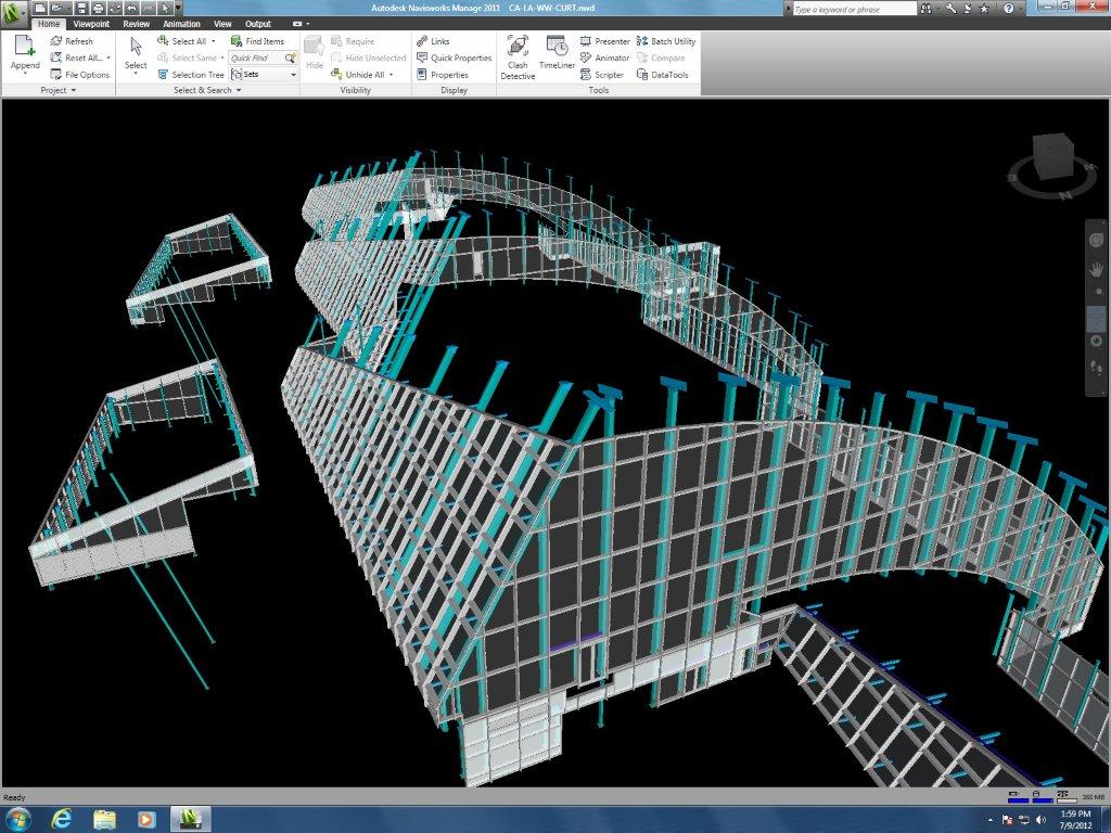
If you create 3d fabrication tickets, you can also pull these into CamPlus to create your machinings.  We find it easier to make individual files that can be reused but for complex parts or especially for compound miters on the Planet, pulling in the fabricated part and using that to make the programming easy is definitely the way to go.  On LAX we had parts with triple compound miters on both ends of the parts.  There was no way to even define the length of those parts most of the time.  By creating the part in Inventor or Autocad and then just importing it into the CamPlus software we were able to create very accurate fabricated parts with no difficulty.


Drum Buffer Rope – A view of pull and flow

Drum Buffer Rope – A view of pull and flow

If you’ve had a chance to read the book “The Goal”, you are probably familiar with Drum, Buffer, Rope.  In the book, the main character observes some boy scouts on a hike.  One of the boy scouts was much slower than the other boy scouts so all of the kids were arriving at different times.  The kids at the front of the pack were getting to the rest stops way ahead of the other kids and the kids behind the slow scout (Herbie) were arriving late because they were behind Herbie.  He experimented with putting the slow kid at different places in the line but he couldn’t get all the kids to the rest stops at the same time.  When he applied this visual to his manufacturing operation, he found a bunch of parallels.  He had various activities happening in his factory but they were all operating at their own pace.  Some were faster, some were slower.  But “the goal” is to get materials that are complete and ready to ship in the most optimized manner.  So he applied the “drum, buffer, rope” concept to his operation.  Drum refers to the pace.  In lean, it would be known as Takt time.  There is an optimum pace that your factory needs to produce items and this optimum pace establishes the takt time or the “drum” in this example.  The rope is the way things are connected.  Each manufacturing operation is tied to the other.  If two activities are tied together, then you want the rope between them to be tight.  If it has slack, then the second activity is going too fast and if it is too tight then the first activity is going too fast.  The buffer is how big the rope is.  How much time between activity one and two?  How much buffer stock or inventory?

In our company, we are working with these ideas.  What is the Takt time in a curtain wall company?  How do we get the various departments and activities to work to that Takt time?  Can we get our vendors to work to our Takt time also?  How do we keep our extruder from shipping us 30-45 days of extrusions (too much buffer)?  How do we get our glass supplier to ship us the glass by day in lieu of large shipments by building?  Can we cut and fabricate just what we need tomorrow?  How would that effect our material optimizations?  Can we assemble and glaze the same number of units that the field will set in a day?  How do we get engineering to match that same pace?

This was one of the things we were considering when we chose our first machine.  In a manual process, people tend to optimize the cutting of like parts because it takes less time.  But this means that materials are not being produced in the same order that the assembly crew or the field installation crew wants them.  With The Planet and the Quadra machines, there is no need to cut all the same parts first.  The machine doesn’t care which parts it makes and does not mind making very different parts right after each other.  With the Emmegi software, we also have the option of sending an optimized list to the machines.  This means that we are not limited to the cutting optimization that the software would normally provide (saw man logic, longest to shortest, etc..) but we can cut our material in the order that it is required even if it means using a bit more metal.

Another advantage that we have now that we are working with our own software is that we have full control of these types of variables.  When we worked with Softtech’s V6 software, we were limited on what we could do with optimizations.  With lean, it is all about optimizing what the customer gets, not creating local optima.  Minimizing waste of metal and creating huge hunting and sorting wastes do not help your customer.

So decide what is creating the beat or takt time through your company.  Link your tasks together using the rope analogy (get them to run at the same pace) and decide how much buffer you need between activities to allow for problems and issues.  Create a smooth flow through your company.  The equipment you choose can greatly help with this.

Our Failed V6 Implementation

At last, I can post this update.  I just migrated my old blog to WordPress and I can finally finish the story of our V6 implementation.

After all the hard work and hours of effort, we decided to scrap using V6 from Softtech.  It was a very tough decision but sometimes you just have to accept that you’ve made a mistake.  Despite all the work and effort to try to get all of the tools in place, it was not getting us where we needed to be.  Speed issues plagued us.  It was cumbersome to set up and tough to train.  Updates to the database were slow.  The shop drawing and VRML outputs were hacks.

My team worked very hard and did their best but in the end, it was just too difficult and we had lots of work that just had to get out the door.  We decided to return to the software we had used originally (a mixture of Autocad and a database back-end).  This got us back on track with the projects, cleaned up the outputs for the shop, and gave us a good starting place to move forward.

The V6 software is probably a better fit for a company that uses standard systems.  We needed something that could work for all the custom projects that we do and also be able to generate the outputs (tickets, cutting lists, machine programming) that we need.

If you don’t have a few failures, you just aren’t trying hard enough.  This was one of my biggest failures.  I learned a ton from the experience and our company is better and stronger because of it.  Our internal development has taken off and the software we are using today is remarkable.  It took a lot of hard work and effort to get here, but I’m very happy with where we are today.

LAX and V6

LAX and V6

I spent the last couple of weeks working with our draftsmen on their V6 projects and the processes we are using. We’re making some great progress here. Our LAX project is an amazingly complex challenge for V6. I’ll try to post some pictures in the near future so you can see what we are doing.We built a plan this week for fabrication tickets on the job. There are approx. 1500 units on the project and over 1000 unit types. The geometry is complex with 5 and 6 sided units, sloped, curved walls, etc… The system is unitized with a pressure plate and face cap and lots of parts and pieces. Over 50 custom dies on the job. Most of the pressure plates and face caps run different than the bodies so you have lots of complexity and notching also.
Our shop is going to produce 80 units per week for about 14 weeks. We built a plan this week to release fabrication tickets, CNC programming and cutting lists in the same weekly cycles. This puts the tickets in our shop’s hands about two months before they are ready to fabricate allowing lots of time for planning. We start tickets on Monday. I’ll keep you posted on our progress.

Engineering Changes

Started our new fiscal year and my goal is to get our engineering process dialed in. We’ve got our implementation of V6 mostly complete but how people use it and the process they go through to be successful still needs to be finalized. So, I’m practicing my lean techniques and going to the Gemba. For the next couple of months I will be sitting with our draftsmen and watching and updating our processes.My first project is Kaiser San Mateo. We had built our elevations in V6 and used these to create our shop drawings. There were numerous changes to the project. So we had to update all of the V6 elevations, create the glass takeoff, molded corner gasket takeoff and miscellaneous takeoff as well as fabrication drawings for 2 different systems.
We started last week. It took about 1.5 days to update all of the elevations. Almost every dimension had changed as well as some of the parts and some captured mullions are now structurally glazed. We then completed the glass, gasket and misc. takeoffs in 2 days. We started on fabrication drawings for the first system on Monday and we should be complete tomorrow.
What I’m finding is that while you can do everything inside of V6, it may not be the most productive thing. Adding milling ops, butt lines and job specific items to the assemblies can be complex and time consuming. Some of these things can be done faster outside of the program. We’re making great progress on this project and I’m learning a lot. I’m hoping to get involved in a new project next so we can work through all of the process.

BIM and V6

When you read the articles and look at the Autodesk information, it leads you to the conclusion that BIM will be a centralized model where all of your information will flow from. Build the model and create your shop drawings. Build the model and get your takeoffs. Build the model and get your CNC information.Our testing with V6 on our first few projects has lead me to a different conclusion. If we were providing standard systems, or electrical systems, or HVAC systems, where the components are predesigned and you are building a model from these components, then the BIM model probably works. Since on most jobs, and especially on the projects that are asking for BIM models, we are providing custom systems, this model doesn’t really work.
We need to be able to create drawings quickly for review. We need to be able to draw out our concepts and get buy-in. If you try to build all of the custom assemblies, build the elevations, then create some drawings to show your customer and then they want to change it or don’t like it, you are wasting a huge amount of time.
Our new paradigm is an Autocad to SoftTech approach. We draw out our profile drawings in Autocad. 2d is much faster to create concepts than 3d. Draw some typical elevations, key in some 2d details and create your profile drawings. Meet with the customer and massage the design until you have exactly what they are looking for. Now build the model.
Most of our customers are expecting that our shop drawings will be a direct result of the model. Instead, we will use the wireframes from the shop drawings to create the model. Shop drawings first, then V6 model, then BIM model in Navisworks. It’s a different direction than they are expecting but it really makes more sense for the type of work we do. We killed ourselves trying to create the models before the shop drawings or at the same time as the shop drawings. It takes time to update the whole model because they want the horizontal body to look different. Oh, and when you submit the changes, they decide they want it different again. Better to work out your ideas in Autocad and then build your V6 model after.
Heading to AU this year. Anyone else going? It would be interesting to meet up and talk about V6. Drop me a line at swatts at waltersandwolf dot com if you’ll be there.